Home › Unlabelled ›
Wiring Diagram For Trailer Lights / Trailer Wiring Diagrams North Texas Trailers Fort Worth - The white wire must be attached to the trailer in order to ground and power the lights.
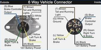
Wiring Diagram For Trailer Lights / Trailer Wiring Diagrams North Texas Trailers Fort Worth - The white wire must be attached to the trailer in order to ground and power the lights.. 5 way trailer wiring diagram allows basic hookup of the trailer and allows using 3 main lighting functions and 1 extra function that depends on the vehicle: 5 wire trailer wiring diagram. Many trailers have three circuits. Featured trailer & caravan parts Right turn signal / stop light (green), left turn signal / stop light (yellow), taillight / license / side marker (brown) and a ground (white).
An extra pin allows using another extra function. Many trailers have three circuits. Trailer wiring diagrams trailer wiring connectors various connectors are available from four to seven pins that allow for the transfer of power for the lighting as well as auxiliary functions such as an electric trailer brake controller, backup lights, or a 12v power supply for a winch or interior trailer lights. The first diagram is a simple set up of two brake lights, two indicators and two side lights. How i rewired my trailer.
Trailer Wiring Diagrams North Texas Trailers Fort Worth from www.northtexastrailers.com See more ideas about trailer wiring diagram, trailer, trailer plans. The four wires control the turn signals, brake lights and taillights or running lights. Here are two wiring diagrams for the 7 pin 'n' type trailer electrical plug. 2013 ford f150 radio wiring diagram sources. If your vehicle is not equipped with a working trailer wiring harness, there are a number of different solutions to provide the perfect fit for your specific vehicle. By law, trailer lighting must be connected into the tow vehicle's wiring system to provide trailer running lights, turn signals and brake lights. It reveals the parts of the circuit as streamlined shapes, as well as the power and also signal links in between the gadgets. The first diagram is a simple set up of two brake lights, two indicators and two side lights.
Right turn signal / stop light (green), left turn signal / stop light (yellow), taillight / license / side marker (brown) and a ground (white).
Some trailer builders just connect this wire to the frame, then connect the ground from all the other lights and accessories to the frame as well. Here are two wiring diagrams for the 7 pin 'n' type trailer electrical plug. Wiring diagram trailers are required to have at least running lights, turn signals and brake lights. The white wire must be attached to the trailer in order to ground and power the lights. How i rewired my trailer. Wiring diagram for trailer lights elegant new wiring diagram ford. Attach the ground wire to the trailer. This video will provide the color layout for a 4 flat connector and a source to get a wiring diagram. Detailed coloured12n trailer wiring diagram which is commonly used on uk and european trailers and caravans from western towing Trailer wiring diagrams trailer wiring connectors various connectors are available from four to seven pins that allow for the transfer of power for the lighting as well as auxiliary functions such as an electric trailer brake controller, backup lights, or a 12v power supply for a winch or interior trailer lights. Many trailers have three circuits. Various connectors are available from four to seven pins that allow for the transfer of power for the lighting as well as auxiliary functions such as an electric trailer brake controller, backup lights, or a 12v power supply for a winch or interior trailer lights. The four wires control the turn signals, brake lights and taillights or running lights.
Let's see what types of connectors the trailer light wiring industry uses today. If there is no red or blue wire and there is both a black & a white wire, normally, the black will be brakes and the white ground. Narva's 'plug and play' waterproof connection system utilises over moulded connectors that quickly join the lamps and trailer plug to the main wiring harness. This car is designed not just to travel one location to another but also to carry heavy loads. Slide the heat shrink over the join and apply heat to seal.
7 Way Trailer Plug Wiring Diagram Hd Trucks Wiring Diagram Book Mute Knot Mute Knot Prolocoisoletremiti It from www.ajtnt.com 4 pin trailer light wiring diagram : Ford f150 trailer wiring harness diagram download. Wiring plug diagram created date: It reveals the parts of the circuit as streamlined shapes, as well as the power and also signal links in between the gadgets. Attach the ground wire to the trailer. S trailer brakes blue lt left turn/brake light yellow rt right turn/brake light green a accessory red the most common variances on this diagram will be the (blue/brake) & (red/acc.) wires will be inverted. This is accomplished by tapping into the tow vehicle's electrical harness to transfer power to the trailer wiring system. Here are two wiring diagrams for the 7 pin 'n' type trailer electrical plug.
It reveals the parts of the circuit as streamlined shapes, as well as the power and also signal links in between the gadgets.
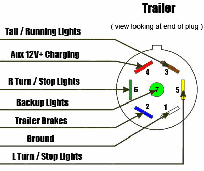
Various connectors are available from four to seven pins that allow for the transfer of power for the lighting as well as auxiliary functions such as an electric trailer brake controller, backup lights, or a 12v power supply for a winch or interior trailer lights. Connect each colour wire on a light to the corresponding wire of the same colour on the trailer wiring. Click on the image below to enlarge it. Cut the white wire short enough for attachment to the front of the trailer near the connector plug. This project requires a trailer lighting kit that includes a wiring harness, small connection clips, a couple rear turn signals and a couple side mounted lights. If your vehicle is not equipped with a working trailer wiring harness, there are a number of different solutions to provide the perfect fit for your specific vehicle. Most of us aren't electricians, but that doesn't mean wiring a trailer or replacing corroded wiring is beyond us. I hope it helps you. 7 way plug wiring diagram standard wiring* post purpose wire color tm park light green (+) battery feed black rt right turn/brake light brown lt left turn/brake light red s trailer electric brakes blue gd ground white a accessory yellow this is the most common (standard) wiring scheme for rv plugs and the one used by major auto manufacturers today. 2013 ford f150 radio wiring diagram sources. A wiring diagram is a streamlined traditional photographic depiction of an electric circuit. The second diagram shows two brake lights, two indicators, two side lights and a fog light. The trailer wiring diagram shows this wire going to all the lights and brakes.
By law, trailer lighting must be connected into the tow vehicle's wiring system to provide trailer running lights, turn signals and brake lights. This is accomplished by tapping into the tow vehicle's electrical harness to transfer power to the trailer wiring system. Trailer wiring diagrams trailer wiring connectors. Trailer wiring diagrams trailer wiring connectors various connectors are available from four to seven pins that allow for the transfer of power for the lighting as well as auxiliary functions such as an electric trailer brake controller, backup lights, or a 12v power supply for a winch or interior trailer lights. Narva's 'plug and play' waterproof connection system utilises over moulded connectors that quickly join the lamps and trailer plug to the main wiring harness.
Trailer Wiring Diagram And Installation Help Towing 101 Trailer Wiring Diagram Trailer Boat Trailer Lights from i.pinimg.com Trailer wiring diagrams trailer wiring connectors various connectors are available from four to seven pins that allow for the transfer of power for the lighting as well as auxiliary functions such as an electric trailer brake controller, backup lights, or a 12v power supply for a winch or interior trailer lights. 12n 7pin trailer & caravan lighting wiring diagram this is the standard uk wiring of a the normal socket and plug otherwise known as 12n. It reveals the parts of the circuit as streamlined shapes, as well as the power and also signal links in between the gadgets. Wiring plug diagram created date: How i rewired my trailer. Attach the ground wire to the trailer. The trailer wiring diagram shows this wire going to all the lights and brakes. Many trailers have three circuits.
They also provide a wire for a ground connection.
Trailer light wiring basics it will help to have an understanding of trailer light systems and we recommend reviewing trailer wiring diagrams before starting this project. Cut the white wire short enough for attachment to the front of the trailer near the connector plug. Right turn signal / stop light (green), left turn signal / stop light (yellow), taillight / license / side marker (brown) and a ground (white). 5 wire trailer wiring diagram. They also provide a wire for a ground connection. Let's see what types of connectors the trailer light wiring industry uses today. Here are two wiring diagrams for the 7 pin 'n' type trailer electrical plug. Various connectors are available from four to seven pins that allow for the transfer of power for the lighting as well as auxiliary functions such as an electric trailer brake controller, backup lights, or a 12v power supply for a winch or interior trailer lights. The white wire must be attached to the trailer in order to ground and power the lights. This project requires a trailer lighting kit that includes a wiring harness, small connection clips, a couple rear turn signals and a couple side mounted lights. Many trailers have three circuits. Just like something, common servicing checks … Trailer wiring diagrams trailer wiring connectors.